ElectricMotorcycleForum.com

  • May 18, 2024, 07:07:20 AM
  • Welcome, Guest
Please login or register.

Login with username, password and session length
Advanced search  

News:

Electric Motorcycle Forum is live!

Show Posts

This section allows you to view all posts made by this member. Note that you can only see posts made in areas you currently have access to.

Topics - Burton

Pages: [1] 2 3 4
1
Buy Sell Trade / Diginow pan NIB
« on: June 03, 2020, 01:33:59 AM »
I have a diginow pan, never used, still in box.

$300 and you pay shipping from NH,USA

Can provide pictures if you require.

2
Buy Sell Trade / SOLD: FS 2017 DSR NH W/ Cases
« on: March 15, 2020, 03:26:29 AM »
SOLD will make a separate post with what is left since bike was largely stock when sold
UPDATE 6/14: Entertaining all serious offers

UPDATE 3/21: Bike returned to stock less listed mods / upgrades / additions. Have a potential buyer next week.

UPDATED (still available) Adding content from other ads here
Open to trades:
non-backhoe heavy equipment (skidsteer [pref. high flow], mini-ex, lull / telehandler)
sprayfoam trailer, gravel screener, etc.
BTC

UPDATED TO REFLECT THINGS I HAVE SOLD SEPARATELY.
IF YOU ARE INTERESTED IN ANY MODS I HAVE ON THE BIKE BELOW MAKE ME AN OFFER AND I WILL REMOVE IT AND MAIL IT TO YOU!

Bike is currently in NH near Littleton

12.0k with everything installed as is right now.
Open to reasonable offers

13,982 miles (mostly highway commuting miles never taken off road)
Garage kept most of the time

What is installed:
* Happy Trails Rack
* Gray stock tank with luggage compartment
* Givi v46 topcase with ~66 LED's
* Givi e21's
* Removable seat mod
* Upgraded horn
* Brake lever modified to activate lights first then physical brakes later.
* airhawk 2 seat

What is not installed but available:SELLING SEPARATELY, Make offers via PM
* Skene design controller IQ160TS
* Accessory circuit for plug in gear and extras
* Waterproof Reverse switch installed but not configured.
* Cycle Analyst HC
* Waterproof interface (3 pin IXXAT out) for controller installed (Have the IXXAT and USB controler capatable for this as well)
* JWSpeaker Evolution Adaptive 2 light and custom bracket
* Black S tank (magnets in place of screws up front so you only have to remove three screws to take it off)
* Diginow ODBII Dongle
* Diginow DIY pan and kit to upgrade to 2.5 + some charging accessories for double J charging. (you would have to modify the existing chargers to mount them on this pan)
* 2 diginow chargers installed in tank (v2.0 I think) with Jplug out side
* 1 more diginow tank charger previously part of a 2 pack for a tank install
* Stock headlight MY13 I think

3
Buy Sell Trade / MY13 tires (new + slicks)
« on: January 18, 2019, 05:14:42 AM »
I have a new set of BT45's for a MY13 S taking up space in my house.
3016 for front tire date 2516 for rear.
I will throw in a pair of racing slicks to fit the same bike for free.

(see attached)

Rather not ship these ... as the cost would be substantial I am sure :/
I am located currently near DC, USA

4
Buy Sell Trade / Meanwell Charging Stack
« on: June 21, 2018, 08:41:45 PM »
Anyone interested in a meanwell stack? This is NOT waterproof ... see other projects in the forum or the large thread here http://electricmotorcycleforum.com/boards/index.php?topic=3987.msg24583#msg24583 which includes images / video / parts lists etc.

Used it for years, no issues. Currently configured to 114.4vdc and produces about 32Amps.
Power connects via anderson powerpolls PP30 and is output via SBS75X connector.
This will not turn your bike on by itself. The way I use this is to either keep the bike on or turn on the stock charger first then connect the aux connector.

Open to reasonable offers.


5
Parts, Mods And Hacks / Mounting Jw Speaker 6in Adaptive 2 Light
« on: May 01, 2018, 09:22:44 PM »
This is version one. I had originally intended to mount this light with fork brackets but they were too small ... so I took a couple hours and whipped this up.

Parts:
1) ~2.5mm / 0.09" 6061 aluminum and feels really solid when installed. ( I cut this with a shaper origin using a milling bit. )
2) Jw Speaker 6" Adaptive 2 (means when high beam is on so is the low beam)
3) Motodemic 6" bucket (they only make one which is side mounted ... you need 8mm 1.25 pitch screws and a spacer ... both which I pulled off another crap bucket I bought which didn't work out ... motodemic will sell you these and the spacer if you ask)

See post 4 for important information on wiring up front!

The attached picture shows how I got basic dimensions for the bracket and the idea of where I am attaching to. In the future I will extend this bracket to better clean up the front end and match the top portion like the stock light does. But for now this is good enough for mounting.

After getting the outline I used a caliper and sketchup to mock up the bracket so I could export a real to size SVG to use in the shaper origin. (shown right)


6
Parts, Mods And Hacks / Installing IXXAT to controller
« on: April 18, 2018, 07:59:53 PM »
I realize this has been done before.

Attached are images of the process. Image 5 on next post. Proceed at your own risk.

Connectors used:
http://www.mouser.com/ProductDetail/harwin/c90-3101f10sl-3p/?qs=uJo%252bpYCWgL4YnPzPO%2fYmdg%3d%3d&countrycode=US&currencycode=USD
C90-3101F10SL-3P
Harwin Circular MIL Spec Connector
US HTS:8536694020 ECCN:EAR99 COO:IN

http://www.mouser.com/ProductDetail/harwin/c90-3106f10sl-3s/?qs=uJo%252bpYCWgL7f5HAxzu8nsA%3d%3d&countrycode=US&currencycode=USD
C90-3106F10SL-3S
Harwin Circular MIL Spec Connector
US HTS:8536694020 ECCN:EAR99 COO:IN

http://www.mouser.com/ProductDetail/harwin/c90-25043-10sl/?qs=uJo%252bpYCWgL4GQy5LYqEkGg%3d%3d&countrycode=US&currencycode=USD
C90-25043-10SL
Harwin Circular MIL Spec Tools, Hardware & Accessories
US HTS:8536694020 ECCN:EAR99 COO:IN

http://www.mouser.com/ProductDetail/cinch-connectivity-solutions/40-9538f/?qs=R4eE4wTkoLA4eYlHed3pYQ%3d%3d&countrycode=US&currencycode=USD
40-9538F
Cinch Connectivity Solutions D-Sub Adapters & Gender Changers
US HTS:8536694040 ECCN:EAR99 COO:CN   

(last connector is RJ45 to DB9 ... Next time I will likely just use a DB9 cable and cut it instead of going this route)

7
Parts, Mods And Hacks / Adding 3.3vdc to OBDII to MY17+?
« on: April 18, 2018, 06:35:04 PM »
I noticed my DigiNow Reaper Dongle didn't work on any MY17 bikes. This is used to log into the MBB and check the status of the bike and adjust settings with a computer.

The issue was the 3.3vdc for OBDII accessories isn't wired from pin 10/40 MBB to pin 12 on the OBDII.

I have included a pdf below for those who feel competent enough to do this modification yourself ...

If the images / text are not enough then you might not currently have the skills required to do this install without potentially damaging your bike.

I make no guarantees this will work on your bike and you are responsible for checking the newly installed pin is indeed 3.3vdc out.

8
General Discussion / Any Weather Warriors out there?
« on: March 20, 2018, 05:20:04 PM »
I ride my bike year round in -10F to 110F rain or in some cases snow.

My general rules for riding are
1) Are the wind gusts over 60mph?
2) Is there Ice / Snow on the ground I cannot dodge?

If either is true I typically will work from home that day ...

Everything else is fair game ... and accepting getting caught in the occasional snow or ice storm is all part of the experience in my book.

But I have always been accepting of the fact my bike doesn't like the rain, cold, or snow ... and it has almost left me stranded a couple times in my 40k+ miles. It often gets me thinking what it would require to make our bikes really weather proof so I wouldn't have to worry about it.

Sitting on the side of the road, next to a median as there are no shoulders, in the pouring rain when it is 40 degrees outside trying to "just get to work" after breaking down because of the rain is not fun.

Are the newer model more rain capable or would I be better served by a ICE bike is often a thought that passes through my mind. Or do I go "extreme" and find another brand and hope for the best?

9
Zero Motorcycles Forum | 2013+ / New Wire Diagram Inbound!
« on: December 11, 2017, 02:47:15 AM »
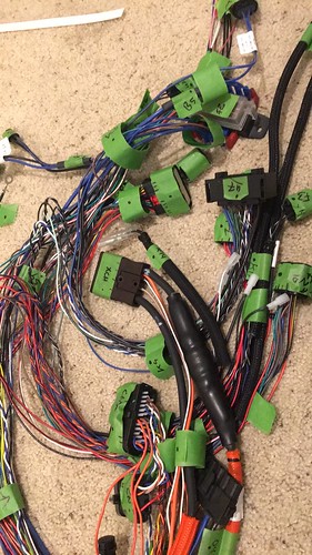
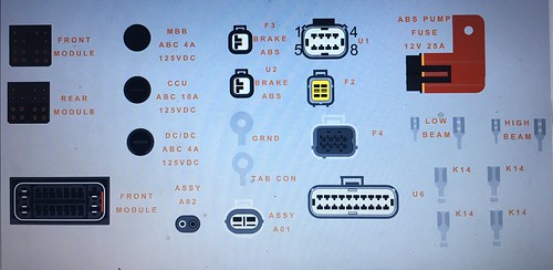
Some of you likely know I have been given a complete wire loom from  and unknown bike and was asked by the giver to document it and make a wire diagram similar to the 2013 zero S / DS diagram I made (see signature for link)

I was going to wait till I had the diagram ready to go but figured sharing the process (again) might be of interest to newer forum members.

I will update this post as I add more video / images.


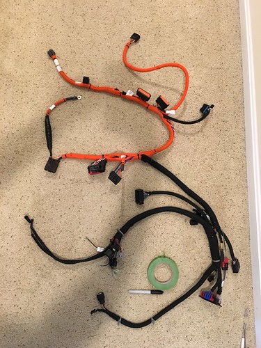
Loom before labels


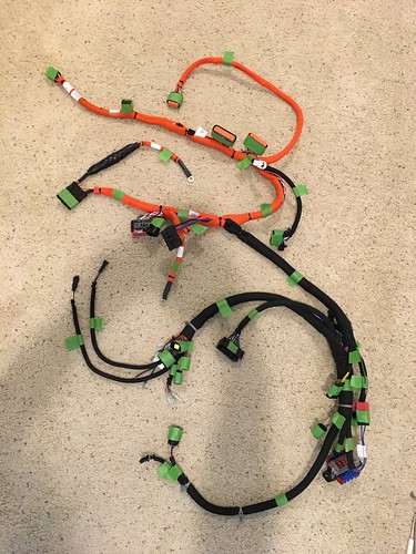
Loom after marking / documenting all connectors (3hrs)


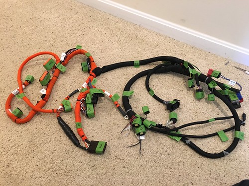
Loom after removing the binding material (1hr)


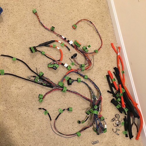
Everything documented ... all ~183 connections (7hrs)


New connectors being made for visio diagram (3hrs)


10
Zero Motorcycles Forum | 2013+ / Sevcon Gen4 Error Codes
« on: May 20, 2017, 08:03:20 AM »
This is only relevant if you have a bike which features a sevcon gen4 controller ...

SOURCE: http://jan.peman.com/hacks/EmergencyErrorCodes.txt

Quote
Emergency (EMCY) codes from the Sevcon Gen4 drives

Can messages looks like this:

ID    b0 b1 b2 b3 b4 b5 b6 b7
"81";"00 31 04 C3 4D 00 00 00"
"81";"00 31 14 C3 4D 00 00 00"
"81";"00 82 10 0F 53 02 00 00"
"82";"00 10 01 54 4F 00 40 00"
"82";"00 10 11 54 4F 00 40 00"
"82";"00 31 04 C2 51 00 00 00"
"82";"00 31 04 C2 51 00 04 00"
"82";"00 31 04 C3 4D 00 00 00"
"82";"00 31 05 C3 4D 00 00 00"
"82";"00 31 15 C3 4D 00 00 00"
"82";"30 81 10 0B 53 01 00 00"

Bytes b1+b0 (switch bytes) describes CanOpen error code according to DS-301

Error code (hex)   Error description
00xx   Error Reset / No Error
10xx   Generic Error
2xxx   Current
3xxx   Voltage
4xxx   Temperature
50xx   Device Hardware
6xxx   Device Software
70xx   Additional Modules
8xxx   Monitoring
90xx   External Error
F0xx   Additional Functions
FFxx   Device Specific

Byte b2 is error register, bit-wise coding, also according to DS-301:

Bit   Error cause
0   Generic Error
1   Current
2   Voltage
3   Temperature
4   Communication Error
5   Device Profile Specific
6   Reserved (always 0)
7   Manufacturer Specific

Bytes b5-b7:
If any of bytes b5-b7 are not 0x00 means error is set. *
If bytes b5-b7 are all 00 it means the error is reset. *
*) might be only b6?

Bytes b4+b3 (switched bytes) describes Sevcon specific errors according to
table below:

0x2401 Login
0x3441 Host SW Upgrade
0x3442 DSP SW Upgrade
0x34C1 Watchdog Reset
0x45C1 BDI Warning
0x45C2 BDI Cutout
0x45c3 Low battery
0x45C3 Low battery
0x45C4 High battery
0x45c5 High capacitor
0x45C5 High capacitor
0x45c6 Vbat below rated min
0x45C6 Vbat below rated min
0x45C7 Vbat above rated max
0x45c8 Vcap above rated max
0x45C8 Vcap above rated max
0x45c9 Motor low voltage
0x45ca Motor high voltage
0x4601 Device too cold
0x4602 Device too hot
0x4603 Motor in thermal c/b
0x4681 Preop
0x4781 Anon EMCY
0x47C1 Service Required
0x4881 Seat
0x4882 Two Dir Fault
0x4883 SRO Fault
0x4884 Sequence Fault
0x4885 FS1 Recycle Fault
0x4941 Low oil
0x4981 Throttle Fault
0x4B81 Anon EMCY
0x4C41 Too Many Slaves
0x4dc3 Supply Critical
0x4F01 Bad State
0x4F02 EMCY Fail
0x4f41 Internal Fault
0x4F41 Internal Fault
0x4F42 Out of Memory
0x4F43 General DSP Error
0x4F44 Timer Error
0x4F45 Queue Error
0x4F46 Sched Error
0x4F47 DSP Heartbeat
0x4F48 IO SS Error
0x4F49 GIO SS Error
0x4F4A LCM SS Error
0x4F4B LCP SS Error
0x4F4C OBD SS Error
0x4F4D VEHAPP SS Error
0x4F4E DMC SS Error
0x4F4F TracApp SS Error
0x4F50 New PF Detected
0x4F51 DSP not detected
0x4F52 DSP Comms Error
0x4F53 App Mgr SS Error
0x4f55 DSP param
0x4F81 Anon EMCY
0x5041 Bad NVM Data
0x5042 VPDO out of range
0x5043 Param fixed range error
0x5044 Param dyn range error
0x5081 Invalid Steer Switches
0x5101 Line Contactor o/c
0x5141 Line Contactor welded
0x5181 Dig In Wire Off
0x5182 Alg In Wire Off
0x5183 Alg Out Over I
0x5184 Alg Out On with No FS
0x5185 Alg Out Off with FS
0x51C1 Power Supply Interrupt
0x51C2 Precharge fail
0x52c1 Encoder fault
0x52c3 Current Control Fault
0x5301 CANbus Fault
0x5302 No Bootup
0x5303 LPRX CAN
0x5304 LPTX CAN
0x5305 HPRX CAN
0x5306 HPTX CAN
0x5307 CAN Overrun
0x5308 CAN Off
0x5309 Nodeguard Error
0x530A PDO Short
0x530B HBeat Error
0x530C CANopen Device State
0x530D CAN Error State
0x530E SDO Handle Error
0x530F SDO Timeout
0x5310 SDO Abort
0x5311 SDO State Error
0x5312 SDO Toggle Error
0x5313 SDO Rx Error
0x5314 SDO Length Error
0x5315 SDO Tx Error
0x5316 CANopen Ev Unknown
0x5317 SDO Bad Source
0x5318 SDO Bad Error No
0x5319 Mtr Slv in Wrong State
0x5341 Wrong DSP protocol
0x5342 Osc WDog Tripped
0x5343 Flt o/flow
0x5381 Anon EMCY
0x54c1 DSP Overvoltage
0x54C1 DSP Overvoltage
0x54C2 DSP PF Fault
0x54C3 Mosfet s/c M1 Top
0x54C4 Mosfet s/c M1 Bottom
0x54C5 Mosfet s/c M2 Top
0x54C6 Mosfet s/c M2 Bottom
0x54C7 Mosfet s/c M3 Top
0x54C8 Mosfet s/c M3 Bottom
0x54C9 Mosfet tests incomplete
0x5741 Invalid Rating
0x5781 Anon EMCY

Example:
ID    b0 b1 b2 b3 b4 b5 b6 b7
"82";"00 31 04 C2 51 00 04 00"

Node id 2 sends emergency error.
Error code: 0x3100 (b1+b0) meaning "Voltage" error category
Error cause: 0x04 (b2) bit 2 set meaning "Voltage" error cause
Sevcon error: 0x51C2 meaning "Precharge fail"


Today while riding home my bike decided to become unresponsive ... nothing new for a vet zero rider who has had similar things happen in a snow storm of all things.

I calmly pull over and wait for the bike to reset. Reassess the situation and decide it is ok to move forward and go home.

I get home and pull my logs twice using dumpall command and reaper dongle. First time somehow the COM6 port connection was lost near end.

Reviewed logs and found Sevcon CAN EMCY Frame error code 0x5182 Uknown in logs. I found the site previously linked and it shows my Analog wire IN was reading "Off" ... this means the voltage was out of range specified as safe in the controller.

From here the controller shows events which disabled then enabled it all within a minute shortly finishing after I had pulled over.

I now know to look at two things (as it doesn't show you which are "off" but does give "data 01 02 00" leading me to assume Analogs mapped to 1 and 2 are suspect ... first the connections leading to my regen lever, and second the connections coming from the step down converter (takes 24vdc to 5vdc for the regen lever)

Somewhere in this circuit the voltage was out of spec long enough for sevcon not to like me :D ...

11
Zero Motorcycles Forum | 2013+ / Joys of Winter Riding
« on: January 13, 2016, 11:08:08 PM »
Description of "fun" event:
Went to work this morning after speed charging the bike to about 85% to prewarm the battery up.

Got to work, shut off the bike, plugged it in, realized I wanted to keep my gloves warm while they sit on bike and restarted bike. This is when I saw an error on the koso display. First it was a 2 4, then a 2 3 where it stayed. And there was 0 SOC displayed even though I know I got there with 50+%.
Gloves were still getting warm so I didn't care, unplugged gloves and put them on, turned bike off and went to work figuring when the bike warms up it will be good.

Get into work and check out error codes in manual ... not good ones to have mind you. I decided to check on the bike to make sure it was charging ... and it is a good thing I did. 

I get to bike to find it still shows a solid green charging light and the 2 3 error blinking. I restart bike and try to connect through reaper dongle ... no luck. I unplug bike and restart.

Display now shows information and there doesn't appear to be an error. I plug bike back in and it starts to charge. I connect through reaper dongle and pull a dumpall then go back to work.


Reviewing the logs:
Reviewing the logs and things get interesting ... and confusing. There are several "throttle" errors but those are kind of common on my bike since I have the regen lever. Then there are lines like this.

Quote
05011                       5   BMS Throt En Wire Disable  vpack = 11619mV, thr_en = 39mV
 05012                      10   Riding                     PackTemp: h-100C, l127C, PackSOC:  0%, Vpack:  0.000V, MotAmps:   0, BattAmps:   0, Mods: 00, MotTemp:-100C, CtrlTemp:-100C, MotRPM:

This appears to have happened when I turned the bike back on after my ride to charge my gloves. I couldn't find any contactor connected line for this event either. And it is worth mentioning I don't think I heard the contactor "release" when turning it off till the 2nd or third restart when I got back to bike just moments ago to check on it.


Quote
510   OB Charger 0 Connected   
 05022                     550   Charging                   PackTemp: h-100C, l127C, PackSOC:  0%, Vpack:2147483.647V, BattAmps:   0, Mods: 00, MbbChgEn: No, BmsChgEn: No

Then we have several lines like this ... like my pack voltage? :/ The temps are way off to from the last reading before the bike acting odd.


Quote
05047                       5   BMS Throt En Wire Disable  vpack = 11619mV, thr_en = 39mV
 05048                      10   Riding                     PackTemp: h-100C, l127C, PackSOC:  0%, Vpack:  0.000V, MotAmps:   0, BattAmps:   0, Mods: 00, MotTemp:-100C, CtrlTemp:-100C, MotRPM:

Eventually we get back to where we "started" with this mess and finally the contactor shows a closed line and I get this


Quote
05073     01/13/2016 09:15:38   Riding                     PackTemp: h 19C, l 18C, PackSOC:100%, Vpack:101.792V, MotAmps:   0, BattAmps:   0, Mods: 10, MotTemp:  18C, CtrlTemp:  11C, MotRPM:   0

This is the current state of the bike but it is "charging" at -12A ... despite showing 100% SOC with 101.7 pack voltage 0_0

Quote
05096     01/13/2016 09:16:16   Charging                   PackTemp: h 19C, l 18C, PackSOC:100%, Vpack:102.136V, BattAmps: -12, Mods: 10, MbbChgEn: Yes, BmsChgEn: No

I have taken the liberty to attach a truncated log file with the relevant bits only for anyone who wishes to dive into this more than I have explained.

I still don't know what went wrong. There was no moisture in the air, it hasn't rained recently. The contactor likely didn't open when the bike shut off ... why this happened idk and I don't have a volt meter attached to the controller to verify this ... but it makes me want to now.

It was 25F if anyone is wondering ... I have ridden the bike without fairings in -10F degree weather before so :/
idk .. suggestions welcome. i hope this doesn't become a pattern. >__<

12
Zero Motorcycles Forum | 2013+ / Pressure Transducer Problems
« on: December 04, 2015, 10:22:30 PM »
Pressure Transducer woes ...

Yesterday while riding home I rolled off my throttle to have my bike starting to regen ... it is programmed not to as I have a footbrake programmed clutch for regen control.

It did this for about 1/4th of my trip (or 1/2 of my highway trip) and then it didn't do it anymore. I thought it would be a loose wire, again, but it returned to normal so I thought I would have to check if it is really regen or just wind resistance today.

Hop on the bike this morning,and find the bike has 100% regen (which is a lot since I have reprogrammed it) when I roll off the throttle ... it is 35F outside.

Roll bike into garage and look at voltage output of the transducer and it is 4.00 ... I squeeze my clutch and it reads 3.89 ... great, a bad transducer I thought.

So I proceed to try and track down my baseline DCF file and cant find it anywhere. Thankfully someone provided me with one and I normalized it between my current save to get a DCF I can roll back to when the transducer breaks (this is my third one mind you)

I get the DCF uploaded and look at the input screen to make sure things are set right to find the transducer at .43vdc >__< ... so my mind is thinking ... ok it really was a loose wire. I roll back yet again to my previous "current" build with the footbrake activated and try to wiggle every wire in the transducer circuit to see if it jumps back up and sticks at 4.0vdc

Nothing I do can reproduce it so I am beginning to think something, be it the transducer, the controller, the dc:dc, is getting cold and messing everything up. My money is on the cheap transducer even though it is filled with oil and not something like water.

Anyone have experience with transducers being fickle in near freezing temperatures??

13
Zero Motorcycles Forum | 2013+ / 2013 to 2014 SR motor swap
« on: November 12, 2015, 05:04:34 AM »
Figured I would start a new thread for this as it is bound to be picture heavy. I will be sure to add it to my content post (found in signature) later.

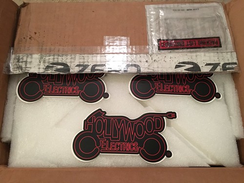
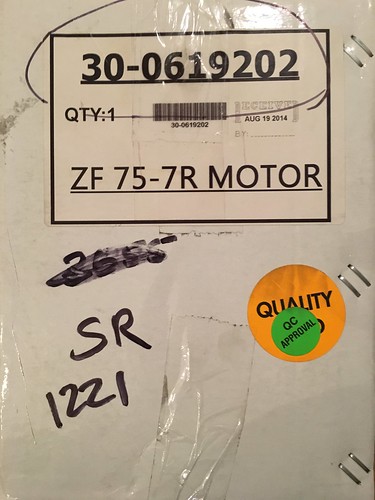
Motor in box, from guess who? It was the last one ... there are no more now.


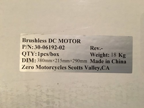
Under all that foam is a white box with the motor. It had several markings.


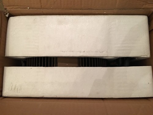
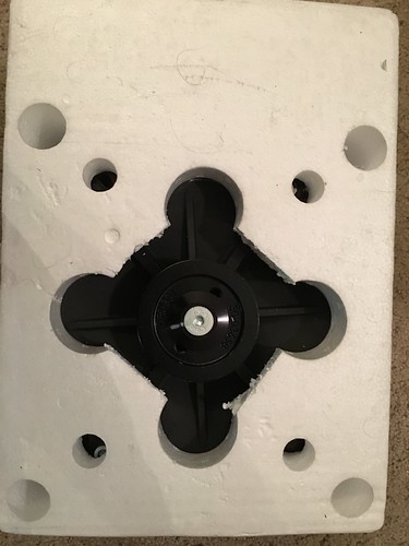
Inside the box the motor was sandwiched between two pieces of foam. I cut both sides and laid the box on the side to push it out ... you know since it weights like 40lbs ;)


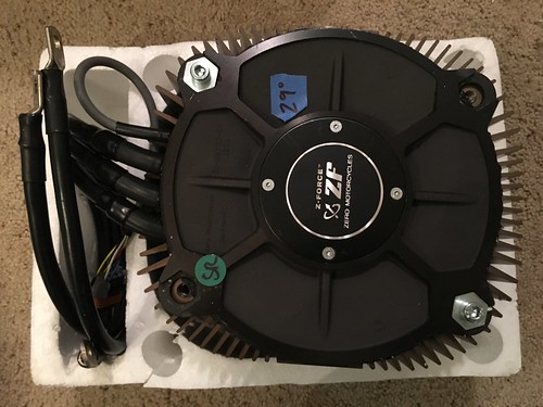
This is the encoder side of the motor in foam.


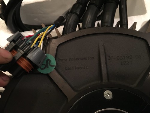
And now sans-foam. You can see the SR sticker, some markings on motor, and a 29 degree sticker (which is the encoder offset used during commissioning). Note two screws to keep plate on :)


Close up of markings. Also the encoder pinout is different than the 2013 I think as there appears to be an extra yellow wire (will have to ask about that)


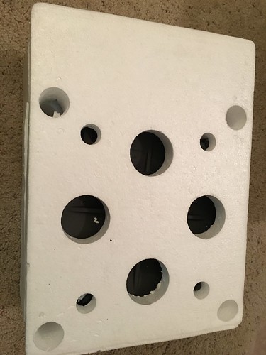
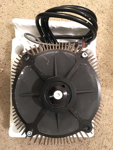
Turning the foam over to pulley side.


And sans foam again two screws to hold plate in place.


The wires are also black and not orange colored. From what I have been told the phases on the motor have the wires shift vs the 2013 motor meaning M1 is the longest vs the 2013 where M1 was shortest. This will require turning the controller around which means removing it, removing the heat sync, and remounting it backwards so the pin out of the controller faces the back of the battery. It will likely not get as wet this way either so it is a win win.

I will likely share more content when friday / saturday roles around as I am climbing tomorrow and don't want to rush the installation without documenting it.

14
General Discussion / What content do you want?
« on: October 26, 2015, 04:29:04 AM »
I want to know where to channel my energy based off what the community wants. This could be documentation, guides, diagrams, video, part lists, or all of the above. What I really want to know though is topics and specifics.

Update: I no longer have a MY13 modified SR and now own a MY17 DSR. I have changed the list to reflect this change.

YET TO DO:
Here are some projects I have on my list of things to do: (in no particular order)
1) Install Vetter fairing on front of bike with the DSR mockup he provided as a guide (ie stock handle bar height)
2) Create DSR mockup "tail" for Vetter setup
7) Custom Kamm tail for Vetter setup.
8) Possibly cutting frame "horns" (where the controller is bolted to) to lower seating for full streamlining
10) Install reverse switch on MY17 DSR
12) Wire Diagram for MY17 DSR
15) Install Vetter turret on MY17 DSR (will require a different mounting solution)
16) Install 3 SC2 chargers on bottom pan of MY17 DSR with 2 J1772 outlets.
17) Install powertank to extend range on MY17 DSR (future)

DONE: (links below)
3) Reinstall my motor (or new motor) when I get the word from Harlan who is checking it out for me. If it is a new motor will likely require encoder calibration and or installation.
4) Clean up wires on top of my battery (my birds nest is on top of battery not behind it) (removed MY13)
5) Custom tank modifications for #4 and possibly other stuff *wink wink nudge nudge say no more*  (removed MY13)
6) Install Brandon's quick tank charger to charge through the controller on 14-50 / J1772 / 15-20 (I haven't purchased it yet since I am waiting on motor news)  (removed MY13, purchased and installed into MY17 tank)
9) Install Cycle Analyst for better data collection (will be needed when I start modifying tail / nose of Vetterized bike)
11) Install 3 pin out for IXXAT on MY17 DSR
13) Install 5.75" bucket on MY17 DSR
14) Create brackets for 5.75" bucket which use stock mounting
18) Install Skene design IQ160TS on MY17 DSR
19) Install Cycle Analyst HC on MY17 DSR
20) MY17+ OBDII 3.3vdc power install

If something you want done isn't on this list suggest it. Just understand my limitation is my bike, a 2013 S / DS / SR (yeah it has a size 6 controller), so I can't do everything you might want to see (less you want to provide a bike for the process). If you think I didn't do a good job of something in the past and want to see more just let me know. I am open for anything if there is enough interest.


For those who are not familiar with my works so far.

Unknown Wire Loom Diagram (in progress):
http://electricmotorcycleforum.com/boards/index.php?topic=7599.0

2013 S / DS Wire diagram:
http://electricmotorcycleforum.com/boards/index.php?topic=3603.msg20961#msg20961

2013 S modified racing motor swap to 2014 SR motor (image heavy)
http://electricmotorcycleforum.com/boards/index.php?topic=5218.0

Clutch "foot brake" install (following evtricity guide) :
http://electricmotorcycleforum.com/boards/index.php?topic=4357.msg27950#msg27950

Most Pin documentation / parts list:
http://electricmotorcycleforum.com/boards/index.php?topic=3987.msg25494#msg25494

Y slitter pin documentation / parts list:
http://electricmotorcycleforum.com/boards/index.php?topic=4603.msg30589#msg30589

RSP Quick charging array and accessories:
http://electricmotorcycleforum.com/boards/index.php?topic=3987.msg24583#msg24583
DIY Charger covers (large project boxes):
http://electricmotorcycleforum.com/boards/index.php?topic=4576.msg30222#msg30222

Replacing bearings on my motor (twice now :/ ):
http://electricmotorcycleforum.com/boards/index.php?topic=4577.msg30227#msg30227

12v Always on pwr srouce :
http://electricmotorcycleforum.com/boards/index.php?topic=3766.msg22451#msg22451

Vetter streamlining project (in progress):
http://electricmotorcycleforum.com/boards/index.php?topic=3618.msg21140#msg21140
http://electricmotorcycleforum.com/boards/index.php?topic=4855.msg32953#msg32953 (image heavy)

Under $50 RFID ignition mod:
http://electricmotorcycleforum.com/boards/index.php?topic=4067.msg25338#msg25338

Controller cover to keep controller warm during winter:
http://electricmotorcycleforum.com/boards/index.php?topic=4274.msg27778#msg27778

2015 AMA State of Electrics Panel:
http://electricmotorcycleforum.com/boards/index.php?topic=4856.msg32954#msg32954

2015 AMA Craig Vetter talking about streamlining:
http://electricmotorcycleforum.com/boards/index.php?topic=4862.msg32970#msg32970

Installation of Cycle Analyst HC model with .25mOhm Shunt: MY13 bike
http://electricmotorcycleforum.com/boards/index.php?topic=3176.msg56253#msg56253

MY17+ OBDII 3.3vdc power supply for diginow dongle
http://electricmotorcycleforum.com/boards/index.php?topic=7908.0

Install IXXAT 3 pin connector
http://electricmotorcycleforum.com/boards/index.php?topic=7909

Create brackets for 5.75" bucket which use stock mounting (v1)
http://electricmotorcycleforum.com/boards/index.php?topic=7943.0


Youtube: 
http://www.youtube.com/callmeburton
Flickr:       
https://www.flickr.com/photos/71805301@N05/

15
Zero Motorcycles Forum | 2013+ / DIY Firmware update?
« on: October 02, 2015, 07:06:24 PM »
Has anyone updated their MBB / BMS firmware themselves?

Local dealer is having issues running some pre test script which is claiming they cannot validate the VIN number. They are also claiming they can't figure out what is wrong because of "some unknown modification," to the bike.

I know the VIN on the bike matches the one at the MBB because I have seen it first hand. I imagine they are running the "test" command at the console but idk what test they are running.

If you have done this yourself please message me ... I am tired of having a nearly bricked bike.

Pages: [1] 2 3 4